At the beginning of this thesis we made the case for separating
the description of an application's functional components from
that of interconnection relationships among the components. We
argued that such a separation will facilitate the development
of new applications from existing software components, and proposed
an outline of a process for developing such applications. The
process is based on applying a series of transformations to an
architectural description of a target application. Chapter 3 introduced
SYNOPSIS, an architectural description language for describing
software applications. This chapter focuses on the transformations
that can be applied to SYNOPSIS architectural diagrams, in order
to generate executable applications. It presents algorithms for
assisting, and in some cases automating, each transformation.
It integrates those algorithms into a concrete implementation
of the process proposed in Chapter 2. Finally, it concludes with
a detailed walkthrough of the process for a concrete example.
In Chapter 2 we proposed an outline of a process for developing
new software applications from existing components. The aim of
this process is to reduce the cost of composing software components
by minimizing the need for ad-hoc, user-written coordination code
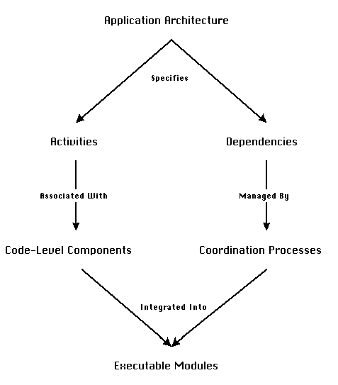
to bridge component mismatches (Figure 5-1).
The process is based on constructing software architecture descriptions,
which clearly distinguish and separate the main functional pieces
of an application from their interconnection relationships in
the context of the application. The process then allows designers
to generate executable applications by applying a set of transformations
to these architectural descriptions.
Chapter 3 focused on the entities of the process (the "nodes"
of Figure 5-1). It introduced SYNOPSIS, an architectural description
language that provides the linguistic tools necessary in order
to build such descriptions. SYNOPSIS describes software applications
as graphs of activities interconnected through dependencies (for
example, see Figure 3-1). Activities specify the main functional
pieces of an application. Dependencies specify interconnection
relationships among activities.
Figure 5-1: A high-level view of a process for
developing component-based software applications (Repeated from
Figure 2-9).
This chapter focuses on the transformation steps of the process
(the "arrows" of Figure 5_1). The practical value of
the proposed process will depend on how easy it is, both to construct
the initial architectural diagrams, and to perform the operations
that transform them to executable code. At best, we would like
as much as possible of the process to be assisted, or automated,
by computerized tools.
For each of the "arrows" in Figure 5-1, section 5.2
will describe:
Section 5.3 will integrate the described system support functions
into an algorithm for semi-automatically generating executable
applications from SYNOPSIS descriptions. Finally, section 5.4
will illustrate its use on a simple example.
5.2 Constructing and Transforming Architectural
Diagrams
There are four stages in the process of Figure 5-1:
The following sections will discuss each stage in detail. For
each stage, we will explore opportunities for assisting or automating
it, and will describe system support necessary for implementing
these opportunities.
5.2.1 Constructing Application Architecture
Diagrams
The first step in the process involves the specification of an
application architecture as a set of activities interconnected
through dependencies. It is important to be able to generate application
architectures rapidly and correctly. The basic requirements for
performing this step include:
a. Linguistic support
SYNOPSIS provides a set of graphical abstractions for defining
activities and dependencies, as well as the linguistic means to
interconnect them (ports and connectors, see Section 3.3). Furthermore,
it supports a compatibility checking mechanism that is able to
detect a number of inconsistencies when connecting elements together
(Section 3.4).
b. Design support
Apart from linguistic support for specifying activities and dependencies,
the construction of application architecture diagrams can be facilitated
by:
Application decomposition can be facilitated by the reuse of generic
decompositions for frequently occurring problems. This requires
the creation of process repositories, or process handbooks,
for storing, searching, and reusing architectural design fragments.
A related project, which is focusing on developing a handbook
of organizational processes is described in [Malone93, Dellarocas94].
SYNOPSIS provides a number of mechanisms for supporting the construction
of process repositories. Architectural patterns can be expressed
as composite activities. Through the mechanism of entity specialization
(Section 3.5), sets of related composite activities can be organized
and stored in a specialization hierarchy. Specialization hierarchies
are similar to class hierarchies in object-oriented system, and
can be used as the basis for structuring repositories of reusable
architectural patterns.
The problem of specifying interdependency patterns among application
activities can be similarly facilitated by a repository of dependency
types for frequently occurring patterns of interaction. One of
the hypotheses of this thesis is that interconnection relationships
can be described using a relatively narrow set of concepts, orthogonal
to the problem domain of most applications. For that reason, we
have attempted to define a standardized, but extensible, vocabulary
of dependency types, that can be used by designers to express
the interaction requirements in their applications. The specialization
mechanism of SYNOPSIS can be used to store and structure the vocabulary
of dependencies. The vocabulary of dependencies is described in
Chapter 4.
5.2.2 Specializing Generic Activities
SYNOPSIS activities can be generic or executable
(see Section 3.3.1). This enables designers to specify the architecture
of their applications at any desired level of abstraction. However,
in order for executable code to be generated, all generic activities
must first be replaced by executable specializations. Executable
atomic activities, also called primitive activities, are
associated with some code-level software component, such as a
source code module, or an executable program. Composite executable
activities decompose into sets of executable elements. Therefore,
the step of replacing generic activities results in the eventual
association of all activities in SYNOPSIS architectural diagrams
with sets of code-level software components.
Although this step is very important, the methodology proposed
in this thesis does not provide specific design guidance on how
to perform it. The responsibility for locating and selecting
the most appropriate code-level components is left with the designer.
We believe that, of all problems related to software reuse, location
of appropriate components is the one that is currently closer
to a satisfactory solution. Several researchers are developing
technologies for collecting software components into component
libraries, easily accessible to the community of designers
[IMSL87, Dongarra87].
Furthermore, new technologies, such as the
Internet, are making a growing number of software component repositories
readily accessible to designers.
Nevertheless, the spirit of the methodology does provide some
leverage for the component selection process because each activity
can be associated to a software component independently of any
other activity. Also, designers do not have to worry about the
specific form of components and their interfaces. Handling of
potential mismatches between component interfaces is completely
contained in the coordination processes that manage dependencies
among components. This facilitates the selection process because
designers need only care about whether a given component contains
the functionality required by its associated activity and not
about how it will fit together with other components already selected.
5.2.3 Specializing Generic Dependencies
One of the novel contributions of this work is the argument that
the functional pieces of a software application and their interdependencies
should be both specified and implemented independently of one
another. In order to generate an executable system, generic dependencies
must be replaced by executable specializations. Executable dependencies
are either directly associated with a software connector, implementing
a low-level interconnection mechanism, or with a coordination
process, defined as a pattern of simpler dependencies and activities
(Section 3.3.2). A large part of this work concentrates on providing
support for assisting, and in some cases automating, the replacement
of dependencies with appropriate specializations.
As with the previous steps, there are two basic requirements for
performing this step:
a. Linguistic support
SYNOPSIS represents coordination processes and software connectors
as attributes of dependencies (see Section 3.3.2). Coordination
processes provide a single home for specifying all the pieces
of an interaction protocol. In contrast, traditional programming
languages usually force the description of interaction protocols
to be distributed among the interacting components.
Coordination processes are defined as compositions of lower-level
dependencies and activities. Furthermore, coordination processes
can be generic or executable. Generic coordination
processes have at least one generic activity, or unmanaged dependency,
in their decomposition. Coordination processes are executable
if all their elements are executable.
Software connectors correspond to low-level interconnection mechanism,
directly supported by programming languages and operating systems
(e.g. procedure calls). Dependencies associated with a software
connector are executable.
b. Design support
i. Assisting the selection of coordination processes
Simply being able to define a coordination process does not tell
designers what should be contained in that process. The biggest
difficulty in building applications from existing components lies
exactly in designing and implementing such coordination software
that bridges mismatches and manages interconnection requirements.
Using current technologies, designers had to almost always build
that software from scratch.
One of the contributions of this work is the development of a
design space of coordination processes for each element of the
vocabulary of dependencies. Chapter 4 contains a detailed description
of the design space. The design space maps each type of dependency
to a family of alternative coordination processes for managing
it. A particular coordination process is selected from that family
by specifying the values of a relatively small number of additional
parameters called design dimensions. For example, a coordination
process for managing a data flow dependency can be selected by
specifying the type of carrier resource (e.g. shared memory, file,
pipe) and the paradigm (push, pull, peer, hierarchy) for managing
the embedded prerequisite (see Section 4.6.2). Some of the alternatives
can be automatically ruled out by compatibility constraints. For
example, when designing a data flow between two components running
under UNIX, only data transport mechanisms supported by UNIX can
be considered as alternatives. This reduces the selection of a
coordination process to a routine selection of a relatively small
number of design parameters.
Most of the coordination processes introduced in Chapter 4 are
defined at the generic level. This means that they are defined
as sets of lower-level generic activities and unmanaged dependencies.
For example, the generic process for managing a one-to-one data
flow dependency (Figure 4-21) consists of two lower-level generic
activities (Manage Usability, Transport Data) and a number of
unmanaged flow dependencies. In order to integrate that process
in an executable application, each of those generic decomposition
elements has to be specialized in turn. Therefore, the previous
candidate selection process has to be recursively applied
to all decomposition elements as well. The design process completes
when all activities and dependencies introduced are executable.
Executable activities have associations with code-level software
components. Executable dependencies are associated to code-level
software connectors, directly supported by specific programming
language or operating system mechanisms (e.g. C procedure calls,
or UNIX pipe protocols).
It is obvious that the above design process can be greatly assisted,
or even automated, by computer. Assuming that there is an on-line
repository of increasingly specialized dependency types, a generic
dependency appearing in a SYNOPSIS diagram can be easily managed
as follows: A design assistant automatically searches the repository
of managed specializations of the generic dependency. It rules
out dependencies whose associated coordination processes are rejected
by the compatibility checking algorithm of Figure 3_15. It then
asks designers to simply select one of the dependencies that pass
the compatibility test. Alternatively, it can present designers
with a set of design dimensions to be specified. If the coordination
process associated to the selected dependency decomposes into
lower-level unmanaged dependencies or generic activities, the
selection process is recursively applied to each of them. Instead
of using recursion, a to-do list can be used to iteratively
store encountered generic activities and unmanaged dependencies,
and then retrieve and handle them until the list becomes empty.
Figure 5-2 shows a flowchart of such an algorithm.
The process described by Figure 5-2 can be fully automated by
allowing designers to specify evaluation functions, or
constraints, that enable the computer to automatically rank candidate
alternatives for each transformation. Such evaluation functions
could be constraints on specific process attributes (e.g. "all
coordination processes must adhere to client/server organizations")
or functions related to the computational cost of coordination
processes. Evaluation functions can further restrict the number
of candidate coordination processes presented to designers. In
some cases, they might restrict the candidates to one, in which
case the selection process becomes fully automatic.
Since the process relies on the existence of a repository of coordination
processes, there might be situations for which no compatible coordination
process has been stored in the repository. For example, when managing
a usability dependency which requires conversion of strings to
integers in Visual Basic, there might be no such specialization
of the conversion activity in the repository. In such cases, the
system asks the users to define a new activity specialization
with that functionality. The specialization typically does not
require more than a few lines of code, and becomes a permanent
part of the repository. In that manner, repositories of design
elements can be incrementally extended and eventually become rich
enough to be able to handle a large number of practical cases.
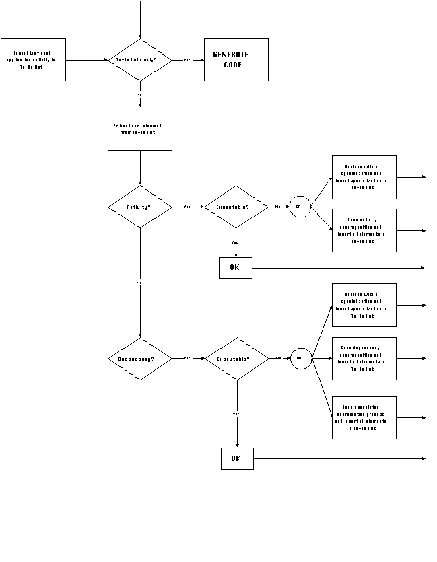
Figure 5-2: An algorithm for iteratively specializing
generic elements in SYNOPSIS architectural descriptions.
ii. Decoupling interface dependencies
The algorithm of Figure 5-2 relies on the assumption that every
dependency in a SYNOPSIS diagram can be managed independently
of every other dependency (unless the designer has explicitly
combined a number of dependencies into a composite dependency
pattern). This assumption is equivalent to the assumption that
the connections of an activity port to other parts of the application
can be managed independently of the connections of every other
port of the same activity.
This assumption, if it holds, has a number of desirable consequences:
Unfortunately, software components built with current technologies
contain interface dependencies among their interface elements
which, unless properly decoupled, would force connections of sets
of activity ports to be jointly managed.
Figure 5-3: An example application where interface dependencies force joint management of flow dependencies.
________________________________________________________________________
Example 5-1:
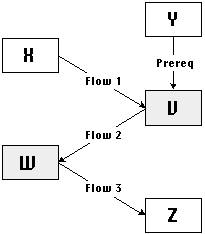
Figure 5-3 shows a fragment of an application architecture. Activities
X, Y, and Z are associated with source code procedures. Activities
V and W are associated with remote servers that can be called
from source code using remote procedure calls (RPCs). At best,
we would like to be able to manage each of the four dependencies
shown in the diagram independently of one another. This would
allow a simple repository of one-to-one coordination processes
to handle this example. However, the semantics of RPC interfaces
place obstacles to this goal.
RPC interfaces expect to receive all their input arguments (plus
control) at the same time, packaged inside a single RPC call.
Moreover, they return all output values to the point of call through
that same interface as well.
Managing dependencies independently of one another requires that
their coordination processes do not share any code. Therefore,
dependency Flow 1 should be able to communicate its value to the
V server without relying on any code introduced by the management
of any other dependency. Likewise, dependency Flow 2 should be
able to access the result of invoking the server independently
of how Flow 1 has been managed. Finally, dependency Prereq should
be able to ensure that Y occurs before V, independently of any
code introduced by the management of either Flow 1 or Flow 2.
Unfortunately, RPC semantics force coordination processes for
all three dependencies to share a common step (the RPC call).
Thus, management of the three dependencies has to be done jointly.
For similar reasons, dependencies Flow 2 and Flow 3 must be jointly
managed. Finally, all four dependencies in the diagram have to
be looked at jointly, in order to be properly managed. In addition
to requiring additional machinery for automatically detecting
them, the existence of such implementation-dependent "dependencies
among dependencies" would require explicit support for
arbitrarily complex composite dependency patterns in the "design
handbook" repository.
_______________________________________________________________________
Figure 5-4: Another example application fragment
with interface dependencies.
Example 5-2:
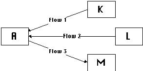
Figure 5-4 shows another fragment of an application architecture.
In this example, A is associated with an executable program for
the Microsoft Windows environment, which expects the existence
of a DDE Server with specific name and interface. In this application,
we are trying to connect the executable with three independent
source procedures, K, L, and M, each of which provides (or receives)
one element of the expected DDE Server interface.
In order to properly connect the source procedures with the executable, they will have to be wrapped together into a DDE Server with a single interface, compatible to the one expected by the executable. This requires the joint management of all three flows appearing in Figure 5-4.
________________________________________________________________________
Examples 5-1 and 5-2 have demonstrated situations in which properties
of specific interface types force the joint management of arbitrarily
complex dependency patterns. Such "dependencies among dependencies"
require both additional machinery in order to be automatically
detected and more complex repositories of coordination processes
in order to be semi-automatically managed.
Interface dependencies are related to the shortcomings of current-technology
code-level components in separating interconnection assumptions
from the implementation of a component's core functionality (see
Chapter 2 for a detailed discussion). They are intrinsic properties
of the code-level components chosen to implement atomic activities.
For that reason, they should be handled at a level orthogonal
to that of managing dependencies among activities.
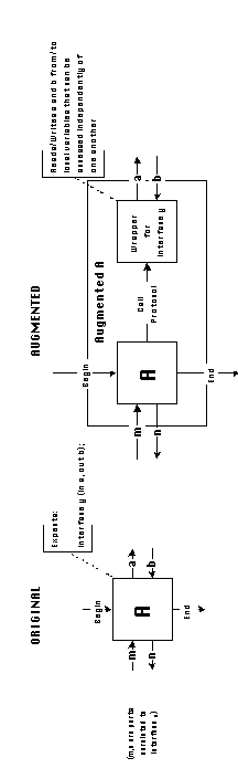
One way of handling interface dependencies is by introducing additional
activities that attempt to decouple them. In other words, before
attempting to manage any dependency, scan primitive activities
and detect interface dependencies among their ports. Whenever
such dependencies are found, replace the original primitive activity
with a composite augmented activity which includes activities
for decoupling ports from one another, allowing them to be independently
managed.
Detecting interface dependencies is easy, because they are inherent
properties of specific interface types. CDL definitions associated
with every primitive activity contain information about the component's
provided interfaces, as well as other interfaces expected
by the component (see Section 3.3.1.2).
Interface definitions involve a set of input and output data elements
(for example, proc foo( in a:Integer, out b:String);
). Each of those elements is mapped to a corresponding atomic
port of the primitive activity. Interface elements are dependent
on one another because they typically have to be combined together
into a single interface call (e.g. a procedure call), or a single
interface header (e.g. a procedure header).
One very general way to decouple interface dependencies is by
transforming complex interfaces to and from sets of local variables.
Each local variable will store one interface element. Since local
variables can be independently read or written, this set of transformations
will enable each input resource to be independently produced and
each output resource to be independently consumed.
The transformations require the introduction of two sets of mediator
activities around primitive activities with interface dependencies:
a. Callers: Activities that read (write) a set of independent
local variables and construct a corresponding call to a given
composite interface.
b. Wrappers: Activities that make a given composite interface
available to the application, and demultiplex its elements into
sets of independent local variables.
Using callers and wrappers, the process of decoupling interface
dependencies among activity ports can be expressed as follows:
For each primitive activity with interface dependencies, structurally
replace it with an augmented activity which, in addition
to the original activity, contains the following mediator activities:
Callers and Wrappers are specified per interface type. In fact,
in order to support a new component kind, designers must specify
appropriate caller and wrapper activities for its associated interface
type.
________________________________________________________________________
Example 5-3:
This example will demonstrate how callers and wrappers can be
defined for a number of common interface types.
a. Source procedure interfaces
If a component provides a source procedure interface, it
can be invoked from inside other blocks of code by simple procedure
calls. The default semantics of procedure calls enable them to
receive their input parameters, and leave their output parameters
to sets of independent variables. For example, in the C language
call statement:
foo(a, b);
a and b are local variables that can be given values by independent
statements preceding the call. As a consequence, provided procedure
interfaces need not be augmented.
If a component expects a source procedure interface, this
means that there is a call to a procedure (defined externally
to the component) with the expected interface from within the
code of the component. Therefore,
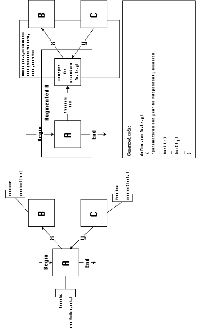
Such components are augmented by the introduction of procedure
wrapper activities. Procedure wrappers translate to source
code headers of procedure calls with the specified name and parameter
list. Activities originally connected to the ports of an expected
procedure interface, will be connected to the wrapper after augmentation
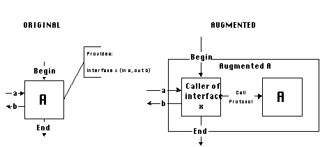
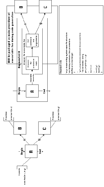
takes place. For example, in Figure 5-7, the component associated
with activity A contains an internal call to procedure foo. In
the application diagram shown, the two parameters x and y passed
to procedure foo by component A, must be independently accessed
by components B and C. During code generation, calls to the components
associated with components B and C will be packaged inside the
body of the procedure defined by the wrapper. Therefore, they
will be able to independently access each procedure call parameter
through local variables.
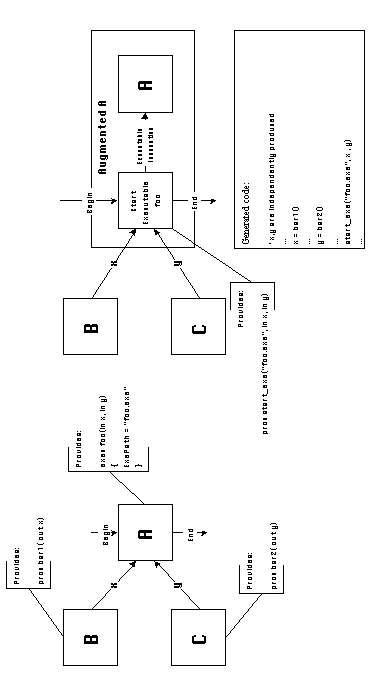
b. Executable program interfaces
Components that provide executable program interfaces,
correspond to executable program files. Caller activities for
executable components are source code procedures which independently
receive all command line parameters necessary to invoke the executable
and construct the appropriate operating system invocation call
(Figure 5-8).
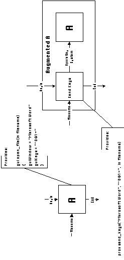
If a component expects an executable program interface,
this means that an executable program with the expected name and
interface is invoked from within the code of the component. Such
components are augmented by the introduction of executable
wrapper activities. Executable wrapper activities translate
to main procedure headers for executable programs with the expected
name and parameter list. In addition, they introduce system-specific
activities which read the command line argument structure passed
to the main procedure by the operating system, and leave each
passed argument to a different local variable. Activities originally
connected to the ports of an expected executable interface, will
be connected to the wrapper after augmentation takes place (Figure
5-9). During code generation, those activities will be packaged
inside the body of the main procedure of the executable defined
by the wrapper. Therefore, they will be able to indedendently
access each command line argument through local variables.
c. Graphical user interface functions
Some programs, designed for interactive use, activate certain
functions when users press a key sequence. For example, a text
editor opens a file when users press CTRL-O, followed by the filename,
followed by newline. In order to integrate such programs into
larger applications, we view them as components that provide a
special kind of interface, called a graphical-user-interface-function
(gui-function). Gui functions specify lists of input parameters,
like any other interface. They also specify a format string, to
which input parameters will be embedded in order to form the activation
key sequence, and a window name, to which the activation key sequence
should be send in order to activate the desired function.
Caller activities for gui functions are source code procedures
which receive the target window name, the format string, and all
input parameters, and use operating system calls in order to send
the activation key sequence to the target window (Figure 5-10).
________________________________________________________________________
There is one special case where the explicit introduction of caller
and wrapper activities might lead to inefficiencies, or even errors.
That is when two of more components with perfectly matching composite
interfaces are connected to each other. In such cases, the composite
pattern of dependencies that specifies the connections among those
interface elements is automatically managed. In order to complete
the support for this step, design assistants should first check
for this special case.
________________________________________________________________________
Example 5-4:
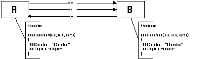
Figure 5-11 shows a fragment of an application architecture in which two activities are connected through a number of flow dependencies. One activity is an executable program expecting a DDE Server and the other is a DDE Server with the exact name and interface expected by the executable. In this special case, all three flow dependencies between the two activities are automatically managed without the need for additional coordination software. Design assistants should be able to check for such special cases and suppress the introduction of caller and wrapper activities when they detect them.
________________________________________________________________________
5.2.4 Integrating Executable Design
Elements into Code Modules
The "raw material" of our component-based application
development process is a set of code-level software components,
in source or executable form. The end product is also a set of
code-level components, consisting of the original components plus
some additional modules containing the coordination software that
manages interdependencies among the original components. The distinction
between activities and dependencies leads to a very useful intermediate
representation, which facilitates the design of the coordination
software. Eventually, however, the original components plus the
new activities and dependencies introduced by the process of design,
must be integrated into sets of source or executable modules.
This section describes this transformation step in more detail
and shows how it can be completely automated.
Following the construction of an initial SYNOPSIS architectural
diagram for a new application, designers proceed by iteratively
specializing activities and dependencies. The process terminates
when all elements of the diagram have been replaced by an executable
specialization.
Executable activities have direct associations with code-level
software components, such as source or executable code modules.
Executable dependencies are associated with built-in language
and operating system interconnection processes, such as the following:
Seq and local variable coordination processes divide the application
graph into a set of partially ordered subgraphs of activities.
Each subgraph contains activities to be packaged into the same
sequential code module.
In order to generate an executable system from a SYNOPSIS graph,
the system must be able to translate that graph into a set of
modules in one or more programming languages. The translation
process has two stages:
a. Connect all sequential modules to control
In order to begin execution, every software module must receive
control from somewhere. This is an application-independent (and
quite obvious) requirement, analogous to the requirement that,
in addition to their configuration-specific interconnections,
all electronic components of a computer system (processor, monitor,
printer, external hard drive, etc.) must also be plugged into
the power network.
The main objective of SYNOPSIS application diagrams is to specify
application-specific constraints among activities, expressed by
flow and timing dependencies, in a more or less declarative fashion.
Activity control ports are connected to dependencies only if the
execution of those activities depends on other activities. To
avoid the cluttering of SYNOPSIS diagrams with unnecessary connectors,
the system enables designers to leave unconnected control ports
of activities that do not depend on any other activities. The
default semantics for such unconnected control ports are that
the respective activities should be started as early as
possible during an application run.
For example, in the File Viewer example application (Figure 3-1)
we have left the Begin ports of activities Select File, Open DB
and Start Viewer unconnected (in fact, we have also made them
invisible). This implies the fact that, execution of those activities
does not depend on any other activity, and should start immediately
upon initiation of the application.
Our design decision to allow the existence of unconnected control
ports in SYNOPSIS has the consequence that, even after all dependencies
have been managed, some of the original and newly introduced modules
might not be connected to a source of control. By default, these
modules should start immediately upon initiation of the application.
Therefore, before code can be generated, those modules have to
be identified and "plugged into the power network",
that is, connected by control flow dependencies to a source of
control. Furthermore, in order to make the invocation of the application
as simple as possible, all application modules must be connected
(by control flows) to a single application entry point
(typically a double-clickable executable file).
One possible packaging strategy that achieves those goals is the
following:
Step 1:
Step 2:
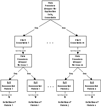
Figure 5-12: Additional activities introduced
by the packaging algorithm.
b. Generate executable code
After the packaging step has been completed, SYNOPSIS graphs can
be translated to sets of modules by a relatively straightforward
process. Primitive coordination processes divide the graphs into
families of partially ordered subgraphs, each corresponding to
a sequential code block. Nodes in these subgraphs correspond to
source code activities, that is, activities that are associated
with source code procedures. Arcs in the graphs correspond to
Seq and local variable primitive coordination processes that impose
ordering constraints and data transfers through local variables.
The code generation process creates a topological sort of each
subgraph (also handling the possibility of loops and branches),
generates a procedure call statement for each activity in the
subgraph, generates and automatically names local variables that
transfer data among procedure call statements in the same subgraph,
and packages all statements and variable definitions into sequential
code blocks for the given language.
The code generator needs to be able to generate the correct syntax
for each source language. Therefore, code generators need some
language-specific knowledge for each language they should be able
to handle. However, the language-specific knowledge required is
quite limited. It basically consists of syntactic rules for generating
procedure calls, declaring local variables, and generating procedure
headers and footers. Support for a new language can thus easily
be concentrated into a single class definition. Section 6.1.5
describes the requirements for supporting a new language in more
detail.
5.3 An Algorithm for Integrating Activities
and Dependencies
This section collects the techniques presented in Section 5.2
into a single algorithm for semi-automatically transforming SYNOPSIS
architectural diagrams into executable applications. Stages 1,
3, and 4 of the algorithm are completely automatic. Stage 2 might
require user input for selecting among multiple candidate processes
or for inputting appropriate processes in cases where none can
be found in the design element repository. Algorithm steps that
require user input have been highlighted in bold typeface.
|
Generate_Application Input: A SYNOPSIS diagram consisting of activities and dependencies
1. Decouple interface dependencies 2. Specialize generic design elements 3. Connect all modules to control
4. Generate executable code |
Stage 1: Decouple interface dependencies
Recursively scan all activities in the application
graph.
For every activity associated with a code-level component,
Scan all provided and expected interface definitions of the associated component.
For every provided interface,
Get the interface kind.
If a caller activity has been defined for that interface kind,
Check for "perfect match" special cases (see Section 5.2.3)
If no "perfect match" interface is found at the other end, |
Stage 2: Specialize generic design elements 2-1 Scan graph and build a to-do list containing, - all generic atomic activities (i.e. atomic activities not associated with a code-level component) - all unmanaged dependencies |
Stage 3: Connect all modules to control


3-1  a.    Scan the application graph and find all source modules that are not connected to a

              source of control.

        b.   Introduce a set of packaging executable components, one per host machine

              and per language for which unconnected source modules exist.

       c.    Package calls to unconnected source modules inside the main program of the

              packaging executable corresponding to the host machine and language of each

              module.

3-2  a.   Scan the application graph and find all executable programs that are not connected

              to a source of control.

        b.   Introduce an application entry executable component into the system.

        c.    Package invocation statements for all unconnected executables inside the main

              program of the application entry component.
|
Stage 4: Generate executable code 4-1 Scan graph and divide into sequential block subgraphs. |
5.4 Generating an Example Application
This section contains a step-by-step description of how the algorithm
of Section 5.3 can generate an executable application by successively
transforming a SYNOPSIS description of its architecture. Our example
will be the File Viewer application that we used to illustrate
the features of the SYNOPSIS language in Chapter 3 (see Figure
3-1).
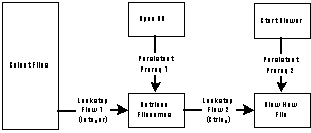
Figure 5-13: A simplified representation of the
File Viewer example application (see Figure 3_1).
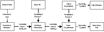
Figure 5-13 shows a simplified version of Figure 3-1 in which dependencies are represented by labeled thick solid arrows. Subsequent figures will show how this initial graph will be successively transformed by the various stages of the algorithm.
Stage 1: Decouple interface dependencies
In this step, the algorithm scans all primitive activities and
augments them with callers and wrappers as necessary.
Activity Select Files is associated with a source code procedure
which expects the existence of another source code procedure with
specified name and interface. A procedure wrapper with appropriate
attributes is inserted to handle this expectation (Figure 5-14(a)).
Activities Open DB and Retrieve Filenames are associated with
simple source code procedures and do not expect any external components.
Therefore, they need not be augmented.
Activity Start Viewer is associated with an executable program. A caller activity that invokes the program is inserted (Figure 5-14(b)). Initially the caller activity is generic, because the system does not yet know in which language to generate the invocation statement. When that information later becomes available, the system will replace this activity with a language-specific executable specialization. The primitive coordination process labeled Operating System, simply states the fact that the operating system is responsible for actually transferring control from the invocation statement to the executable program.
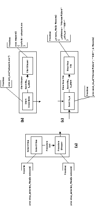
Figure 5-14: Augmentation of activities of File
Viewer application by inserting caller and wrapper activities.
Finally, activity View New File is a graphical-user-interface
function, which is activated through a keystroke sequence. A caller
activity that sends the appropriate keystroke sequence, and therefore
activates the function, is inserted (Figure 5-14(c)). As before,
the caller activity is initially a generic one, to be replaced
by a language-specific executable specialization when more information
becomes available.
After Stage 1 has been completed, the original application graph
of Figure 5-13 has been transformed to the one shown in Figure
5-15. Primitive coordination processes are represented by dotted
arrows.
Stage 2: Specialize generic elements
The graph of Figure 5-15 contains the following generic elements
that must be either specialized or managed:
| Generic activities | Unmanaged dependencies |
| Start Executable
Send Keystrokes | Lockstep Flow 1
Lockstep Flow 2 Persistent Prereq 1 Persistent Prereq 2 |
Stage 2 of the design algorithm successively handles each of the
above elements.
Let us first look at the management of dependency Lockstep Flow
1. Chapter 4 contains a detailed discussion of coordination processes
for flow dependencies. The algorithm would first manage the dependency
with a generic flow coordination process, like the one shown in
Figure 5-16(a). That process introduces additional dependencies
and generic activities that must be recursively specialized. Chapter
4 describes a number of alternative ways of specializing the Transport
Data activity. Those alternatives could have been organized in
a repository of coordination processes as shown in Figure 5-17.
Flow 1 specifies a flow between two procedures written in different
languages (C and Visual Basic), which must be placed in different
executable programs on the same host machine. Therefore, we must
select a mechanism that is able to handle such cases. Microsoft
Windows provides a protocol called Dynamic Data Exchange (DDE)
to support such data exchanges. DDE transfer, however, only supports
the exchange of string data, while in this flow we are transporting
integer code numbers. The solution lies in specializing the management
of the usability dependency in order to translate integers to
and from strings (which act as an "interchange format"
in this simple case, see Section 4.5.1). The final decomposition
of the coordination process for managing Flow 1 is shown in Figure
5-16(b).
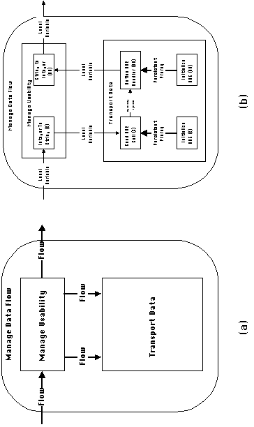
Figure 5-16: Generic and specialized processes
for managing dependency Lockstep Flow
1.
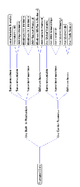
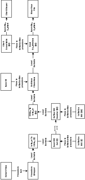
Figure 5-18 shows the File Viewer application graph after replacing
Flow 1 with the coordination process of Figure 5-16(b).
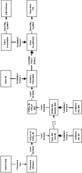
Figure 5-18: File Viewer application graph after
managing dependency Lockstep Flow 1.
The remaining unmanaged dependencies can be managed in a similar
fashion:
If we replace generic activity Send Keystrokes with its executable
Visual Basic version, dependency Lockstep Flow 2 will be connecting
two Visual Basic procedures. Therefore it can be trivially managed
by packaging the calls to the two procedures inside another procedure
and using local variables to transfer the data between them.
Figure 5-19 shows an excerpt from a repository of processes for
managing persistent prerequisites. In this example, we choose
to manage them simply by placing the precedent activities in the
initialization procedure of their respective executable
programs. The initialization procedure has the predefined name
Init_<language> and is automatically placed before
any other statement in the main procedure of the corresponding
executable program by the code generator (Stage 4).
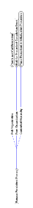
Figure 5-19: An excerpt of a coordination process
library for managing persistent prerequisite dependencies.
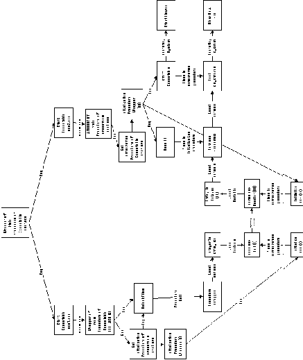
Figure 5-20 shows the application graph after all above transformations
have taken place. At this stage, all activities and dependencies
have been replaced with executable specializations.
Stage 3: Connect all modules to
control
This stage begins by scanning all activities in order to detect
the ones that do not receive control from anywhere else in the
graph. In the diagram of Figure 5-20 such activities are the ones
that have no arrow going into them. These activities are:
| Activity Name | Language | Comments |
| Select Files | C | |
| Initialize DDE (C) | C | to be packaged inside initialization procedure of C executable |
| Initialize DDE (VB) | VB | to be packaged inside initialization procedure of Visual Basic executable |
| Open DB | VB | same as above |
| Start Executable (VB) | VB | same as above |
One possible strategy for connecting those activities to control
is the following:
A new executable program is created for each of the languages
in which exist unconnected modules. In this application, unconnected
source modules exist in two different languages: C and Visual
Basic. Therefore, the system will create two new executables:
Each of the two executables will begin its execution from its
main program. The main program will contain calls to:
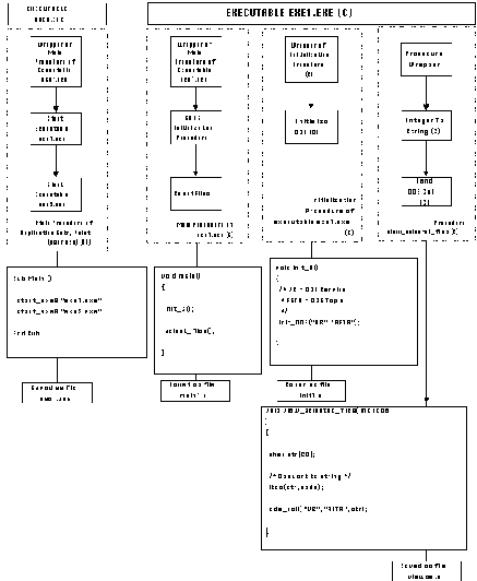
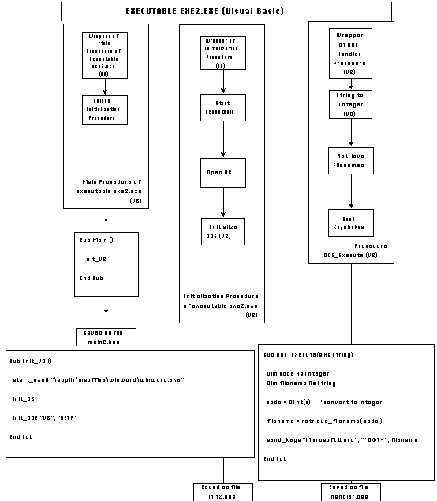
In our example, the main procedure of exe1, written in C, packages calls to procedure Init_C and procedure select_files. The main procedure of exe2, written in Visual Basic, only packages a call to procedure Init_VB.
Finally, in order to be able to start the entire application from
a single point, invocation statements for both executables will
be packaged together inside the main program of yet another executable
(user.exe) which will start the application.
Figure 5-21: Packaging activities introduced by Stage 3.
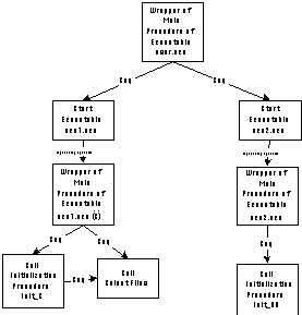
The packaging activities introduced by this stage of the algorithm
are shown in Figure 5_21. The resulting application graph after
all the previous transformations have been applied is shown in
Figure 5-22.
The algorithm is now ready to transform the application graph
into executable code. This is performed as follows:
The resulting set of executables can be invoked simply by double-clicking
the executable file user.exe.
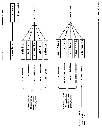
Figure 5-24: Final set of source and executable
files for the File Viewer example application.
This chapter has concluded the description of the elements of
the proposed process for developing component-based software applications.
Our next two tasks are, to provide evidence for its feasibility
and practical usefulness, and to compare it with related research
efforts.
Chapter 6 begins with a description of SYNTHESIS, a prototype
application development system that implements the ideas presented
in Chapters 2-5 and demonstrates that they can indeed form the
basis of a computer-assisted methodology for developing component
based applications. The rest of the chapter describes our experiences
from using SYNTHESIS to design four example applications.
Finally, Chapter 7 is devoted to a discussion of related research.